Read But How Do It Know? - the Basic Principles of Computers for Everyone Online
Authors: J Clark Scott
But How Do It Know? - the Basic Principles of Computers for Everyone (8 page)

And the chart that shows how it operates looks like this:
| | | | |
| | | | |
| | | | |
| | | | |
| | | | |
| | | | |
| | | | |
| | | | |
| | | | |
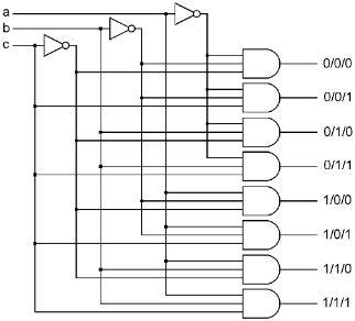
Imagine replacing input ‘c’ with another AND gate, then you would have a four input AND gate. You could then replace any of the four inputs with another AND gate, and have a five input AND gate. This can be done as many times as necessary for what you are doing.
As you add inputs, the chart will need more and more lines. Every time you add another input, you double the number of combinations that the inputs can have. The chart we saw for the original two input AND gate had four lines, one for each possibility. The three input, directly above, has eight lines. A four input AND gate will have 16 lines, a five input will have 32, etc. In all cases though, for an AND gate, only one combination will result in the output turning on, that being the line where all inputs are on.
Here is the last combination we need to make the first half of a computer. This combination is different from anything we have looked at so far, in that it has more outputs than inputs. Our first example has two inputs and four outputs. It is not very complicated, it just has two NOT gates and four AND gates.
In the diagram below, ‘a’ and ‘b’ are the inputs coming in from the left. Both of them are connected to NOT gates. The NOT gates generate the opposite of their inputs. There are four vertical wires going down the page that come from ‘a’ and ‘b’ and the opposites of ‘a’ and ‘b.’ Thus, for each ‘a’ and ‘b,’ there are two wires going down the page, where one of them will be on if its input is on, and the other will be on if its input is off. Now we put four AND gates on the right, and connect each one to a different pair of the vertical wires such that each AND gate will turn on for a different one of the four possible combinations of ‘a’ and ‘b.’ The top AND gate, labeled “0/0” is connected to the wire that is on when ‘a’ is off, and the wire that is on when ‘b’ is off, and thus turns on when ‘a’ and ‘b’ are both 0. The next AND gate, “0/1” is connected to the wire that is on when ‘a’ is off, and ‘b,’ so it turns on when ‘a’ is 0 and ‘b’ is 1, etc.
The inputs can be on in any combination, both bits off, one on, the other on, or both on. None, one or two on. The outputs, however, will always have one and only one output on and the other three off. The one which is on is determined by the current states of ‘a’ and ‘b.’

| | | | | | |
| | | | | | |
| | | | | | |
| | | | | | |
| | | | | | |
This combination is called a decoder. The name means that if you consider the four possible states of the two inputs as a code, then the output tells you which of the codes is currently on the input. Maybe it’s not a great name, but that’s what it meant to someone once, and the name stuck. This decoder has two inputs, which means that there can be four combinations of the states of the inputs, and there are four outputs, one corresponding to each of the possible input combinations.
This can be extended. If we added a third input, there would then be eight possible input combinations, and if we used eight, three input AND gates, we could build a three input, eight output decoder. Similarly, we could build a four input, 16 output decoder. Decoders are named by the number of inputs “X” the number of outputs. Like 2X4, 3X8, 4X16, 5X32, 6X64, etc.
Again, we will simplify our drawings, we won’t show any of the internal parts or wiring, we’ll just have a box with a name and the inputs and outputs that we are interested in. We have seen how NAND gates make NOT gates and AND gates, and then NOT gates and AND gates make a Decoder. It is a box full of NAND gates wired up to do something useful. We know what it does, one and only one of the outputs is always on, and which one it is, is determined by the state of the three inputs. That’s all it does.

First Half of the Computer
Lets build something with the parts we have so far. Actually, we can now build fully half of what’s in a computer.
First, let’s build something similar out of wood (in our minds,) then we’ll come back and show how to build a computer version that does pretty much the same thing.
You know in a hotel, at the front desk, on the wall behind the clerk, there are a series of little wooden cubbyholes, one for each room in the hotel. That’s where they keep extra room keys and messages or mail for the guests. Or you may have seen an old movie where someone in an old post office was sorting the mail. He sits at a table with a series of cubbyholes at the back. He has a pile of unsorted mail on the table, picks up one at a time, reads the address, and puts the letter in the appropriate cubbyhole.
So we’re going to build some cubbyholes. Ours will be three inches square, and there will be sixteen cubbyholes high and sixteen cubbyholes across. That’s a total size of four feet by four feet, with a total of two hundred fifty six cubbies.
Now we’ll add something that they don’t have in the post office or the hotel. We’re going to put a large wood panel right in front of the cubbies which is twice as wide as the whole thing, and in the middle it has a vertical slot that is just large enough to expose one column of 16 cubbies. The panel will have wheels on the bottom so it can slide left and right to expose any one of the vertical columns of sixteen cubbies at a time, and cover all of the other columns.
Let’s take another wood panel just like the first, but turn it up sideways so it is twice as high as our cubbyholes, and the slot in the middle goes side to side. This second panel will be mounted right in front of the first, in something like a window frame, so it can slide up and down, exposing just one row of sixteen cubbies at a time.
So now we have a series of 256 cubbyholes, and two slotted wooden panels in front of them that allow only one cubby at a time to be visible. In each of these cubbies, we will place a single slip of paper on which we will write one of the possible combinations of eight zeros and ones.
This cubbyhole device has 256 places to store something. At any given time, we can select one and only one of those places by sliding the wood panels side to side or up and down. At the selected cubbyhole, we can reach in and get the slip of paper and read it, or replace it with another one.
Now we will take the gates, registers and decoders that we have described, and make something out of them that does pretty much the same thing as our cubbyhole device. This thing will have 256 places in which to store something, and we will be able to select one and only one of those places at any given time.
Referencing the diagram below, we start with a single register. Its input ‘a,’ is a bus that comes from somewhere else in the computer. A combination of bits is placed on the bus and the ‘sa’ (set a) bit goes 1 then 0. That bit pattern is now stored in this register, which is one of those registers whose output is always on. The first four output bits are connected to one 4X16 decoder, and the other four output bits are connected to another 4X16 decoder. The outputs of the two decoders are laid out in a grid pattern. The wires do not touch each other, but there are 16 by 16, or 256 intersections here that we will make use of soon. A decoder, as stated, has one and only one of its outputs on at any time, and the rest are off. Since we have two decoders here, there will be one horizontal grid wire on, and one vertical grid wire on. Therefore, of these 256 intersections, there will be only one intersection where both the horizontal and vertical wires are on. Which intersection that is will change every time the value in R is changed, but there will always be one where both wires are on while the other 255 will have only one on or none on.